IDLgrImage objects have the following properties in addition to properties inherited from any superclasses. Properties with the word “Yes” in the “Get” column of the property table can be retrieved via IDLgrImage::GetProperty. Properties with the word “Yes” in the “Init” column of the property table can be set via IDLgrImage::Init. Properties with the word “Yes” in the “Set” column in the property table can be set via IDLgrImage::SetProperty.
Note: For a discussion of the property description tables shown below, see Modifying Object Property Descriptions.
Objects of this class have the following properties. See IDLgrImage Properties for details on individual properties.
In addition, objects of this class inherit:
ALL
An anonymous structure containing the values of all of the properties associated with the state of this object. State information about the object includes things like color, range, tick direction, etc., but not image, vertex, or connectivity data, or user values.
Note: The fields of this structure may change in subsequent releases of IDL.
Note: This structure returns a COLOR property that is consistent with other graphic objects. However, as an image object’s color depends on each sample of data, the concept of an overall COLOR is not meaningful for this object and is not used in rendering the object.
|
Property Type
|
Structure |
|
Name String
|
not displayed
|
|
Get: Yes |
Set: No |
Init: No |
Registered: No
|
ALPHA_CHANNEL
A floating-point value in the range [0.0, 1.0] to specify the opacity of the image. The default value of 1.0 causes IDL to draw the image completely opaque. If the value of this property is less than 1.0, then the pixels of the image are blended with the pixels already on the screen, where the image is blended according to the values in the BLEND_FUNCTION property.
Note: If a SHADER is associated with the image object, the ALPHA_CHANNEL value is ignored.
Because an object can only be blended with objects already drawn on the screen, the drawing order of the objects must be considered carefully in order to obtain the desired results.
This property has no effect on devices using indexed color model.
If the image data contains an alpha channel, the effective alpha of each pixel is the pixel’s alpha multiplied by the value in the ALPHA_CHANNEL property.
Since the BLEND_FUNCTION property contributes (along with the value of the ALPHA_CHANNEL property) to the control of the blending, be sure to set the BLEND_FUNCTION property to the desired value. Its default value is [0,0]. To obtain the same blending function used by other graphic objects using the ALPHA_CHANNEL property, set the BLEND_FUNCTION property to [3,4].
|
Property Type
|
Float-point value
|
|
Name String
|
Opacity |
|
Get: Yes |
Set: Yes |
Init: Yes
|
Registered: Yes
|
BLEND_FUNCTION
A two-element integer vector that controls how the alpha channel values will be interpreted. Set this property equal to a two-element vector [src, dst] specifying one of the functions listed below for each of the source and destination objects. These are only valid for RGB model destinations. If an alpha channel is not specified in an image, the image’s alpha blend factor is assumed to be 1.0. The values of the blending function (Vsrc and Vdst) are used in the following equation
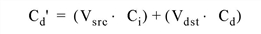
where Cd is the initial color of a pixel on the destination device (the background color), Ci is the color of the pixel in the image, and Cd' is the resulting color of the pixel.
Setting src and dst in the BLEND_FUNCTION vector to the following values determine how each term in the equation is calculated:
|
src or dst |
Vsrc or Vdst
|
What the function does
|
|
0 |
n/a |
Alpha blending is disabled, which is the default setting. Cd' = Ci
|
|
1 |
1 |
The value of Vsrc or Vdst in the equation is one, thus the value of the term is the same as the color value.
|
|
2 |
0 |
The value of Vsrc or Vdst in the equation is zero, thus the value of the term is zero.
|
|
3 |
Imagea
|
The value of Vsrc or Vdst in the equation is the blend factor of the image’s alpha channel.
|
|
4 |
1-Imagea
|
The value of Vsrc or Vdst in the equation is one minus the blend factor of the image’s alpha channel.
|
For example, setting BLEND_FUNCTION = [3, 4] creates an image in which you can see through the foreground image to the background to the extent defined by the alpha channel values of the foreground image.
Since the alpha blending operation is dependent on the values of pixels already drawn to the destination for some blending functions, the final result may depend more on the order of drawing the images, and not necessarily on their relative location along the Z axis. IDL draws images in the order that they are stored in the IDLgrModel object that contains them.
This property is registered as a user-defined property, but it is hidden by default.
|
Property Type
|
USERDEF |
|
Name String
|
Blend function |
|
Get: Yes |
Set: Yes |
Init: Yes
|
Registered: Yes
|
CHANNEL
A hexadecimal bitmask that defines which color channel(s) to draw. Each bit that is a 1 is drawn; each bit that is a 0 is not drawn. For example, 'ff0000'X represents a Blue channel write. The default is to draw all channels, and is represented by the hexadecimal value 'ffffff'X.
Note: This property is ignored for CI destination objects.
This property is registered, but it is hidden by default.
|
Property Type
|
Integer |
|
Name String
|
Color channel |
|
Get: Yes |
Set: Yes |
Init: Yes
|
Registered: Yes
|
CLIP_PLANES
A 4-by-N floating-point array of dimensions [4,N] specifying the coefficients of the clipping planes to be applied to this object. The four coefficients for each clipping plane are of the form [A, B, C, D], where Ax + By + Cz + D = 0. Portions of this object that fall in the half space Ax + By + Cz + D > 0 will be clipped. By default, the value of this property is a scalar (-1) indicating that no clipping planes are to be applied.
Note: The clipping planes specified via this property are applied in addition to the near and far clipping planes associated with the IDLgrView in which this object appears.
Note: Clipping planes are applied in the data space of this object (prior to the application of any x, y, or z coordinate conversion).
Note: To determine the maximum number of clipping planes supported by the device, use the MAX_NUM_CLIP_PLANES keyword of the GetDeviceInfo method for the IDLgrBuffer, IDLgrClipboard, IDLgrWindow, and IDLgrVRML objects.
|
Property Type
|
Floating-point array
|
|
Name String
|
not displayed
|
|
Get: Yes |
Set: Yes |
Init: Yes
|
Registered: No
|
DATA
A n x m, 2 x n x m, 3 x n x m, or 4 x n x m array (any type) of image data for the object. The n and m values may be in any position as specified by the INTERLEAVE property.
Specifying this property is the same as specifying the optional ImageData argument to the IDLgrImage::Init method.
Note: IDLgrImage does not treat NaN data as missing. If the image data includes NaNs, it is recommended that the BYTSCL function be used to appropriately handle those values. For example:
oImage->SetProperty, DATA = BYTSCL(myData, /NaN, MIN=0, MAX=255)
|
Property Type
|
Array of any type
|
|
Name String
|
not displayed
|
|
Get: Yes |
Set: Yes |
Init: Yes
|
Registered: No
|
DEPTH_OFFSET
This property only has an effect when the image is rendered with a texture-mapped polygon and depth testing is enabled.
Set this property to an integer value that specifies an offset in depth to be used when rendering images. This offset is applied along the viewing axis, with positive values moving the image away from the viewer.
The units are “Z-Buffer units,” where a value of 1 is used to specify a distance that corresponds to a single step in the device’s Z-Buffer.
Use DEPTH_OFFSET to always cause an image to be rendered slightly deeper than other primitives, independent of model transforms. This is useful for avoiding stitching artifacts caused by rendering lines or polygons on top of images at the same depth.
Note: Use this feature to remove stitching artifacts and not as a means for “layering” complex scenes with multiple DEPTH_OFFSET values. It is safest to use only a DEPTH_OFFSET value of 0, the default, and one other non-zero value, such as 1. Many system-level graphics drivers are not consistent in their handling of DEPTH_OFFSET values, particularly when multiple non-zero values are used. This can lead to portability problems because a set of DEPTH_OFFSET values may produce better results on one machine than on another. Using IDL’s software renderer will help improve the cross-platform consistency of scenes that use DEPTH_OFFSET. However, software rendering may reduce the rendering performance of images displayed as texture-mapped polygons.
|
Property Type
|
Integer |
|
Name String
|
Depth offset |
|
Get: Yes |
Set: Yes |
Init: Yes
|
Registered: Yes
|
DEPTH_TEST_DISABLE
An integer value that determines whether depth testing is disabled.
- Set this property to 0 to inherit the value set by the parent model or view. The parent view always enables depth testing. A model may also enable or disable depth testing.
- Set this property to 1 (the default) to explicitly disable depth buffer testing while drawing this object.
- Set this property to 2 to explicitly enable depth testing for this object.
Disabling depth testing allows an object to draw itself on top of other objects already on the screen, even if the object is located behind them.
Note: To preserve backward compatibility with previous versions of IDL the default value of this property is different from that of other graphic objects using this property.
Note: Disabling depth testing also disables depth buffer writing. When disabling depth testing, the DEPTH_TEST_FUNCTION, DEPTH_OFFSET, and DEPTH_WRITE_DISABLE properties are effectively ignored.
This property is registered as an enumerated list, but it is hidden by default.
|
Property Type
|
ENUMLIST |
|
Name String
|
not displayed
|
|
Get: Yes |
Set: Yes |
Init: Yes
|
Registered: No
|
DEPTH_TEST_FUNCTION
An integer value that determines the depth test function. Set this property to 0 (the default) to inherit the value set by the parent model or view. The parent view always sets a depth test function of LESS. A model may also set a depth test function value. The graphics device compares the object’s depth at a particular pixel location with the depth stored in the depth buffer at that same pixel location. If the comparison test passes, the object’s pixel is drawn at that location on the screen and the depth buffer is updated (if depth writing is enabled).
Set this property to any of the following values to use the desired function while rendering this object.
- 0 = INHERIT - use value from parent model or view.
- 1 = NEVER - never passes.
- 2 = LESS - passes if the object’s depth is less than the depth buffer’s value.
- 3 = EQUAL - passes if the object’s depth is equal to the depth buffer’s value.
- 4 = LESS OR EQUAL - passes if the object’s depth is less than or equal to the depth buffer’s value.
- 5 = GREATER - passes if the object’s depth is greater than or equal to the depth buffer’s value.
- 6 = NOT EQUAL - passes if the object’s depth is not equal to the depth buffer’s value.
- 7 = GREATER OR EQUAL - passes if the object’s depth is greater than or equal to the depth buffer’s value.
- 8 = ALWAYS - always passes
Less means closer to the viewer.
This property is registered as an enumerated list, but it is hidden by default.
|
Property Type
|
ENUMLIST |
|
Name String
|
not displayed
|
|
Get: Yes |
Set: Yes |
Init: Yes
|
Registered: No
|
DEPTH_WRITE_DISABLE
An integer value that determines whether depth writing is disabled.
- Set this property to 0 (the default) to inherit the value set by the parent model or view. The parent view always enables depth writing. A model may also enable or disable depth writing.
- Set this property to 1 to explicitly disable depth buffer writing while rendering this object.
- Set this property to 2 to explicitly enable depth writing for this object.
Disabling depth writing allows an object to be overdrawn by other objects, even if the object is located in front of them.
This property is registered as an enumerated list, but it is hidden by default.
|
Property Type
|
ENUMLIST |
|
Name String
|
not displayed
|
|
Get: Yes |
Set: Yes |
Init: Yes
|
Registered: No
|
DIMENSIONS
Set this property to a two-element integer vector of the form [width, height] specifying the dimensions of the rectangle in which the image is to be drawn on the device. The image will be resampled as necessary to fit within this rectangle. The default is derived from the dimensions of the given image data and is measured in pixels. IDL converts, maintains, and returns this data as double-precision floating-point.
Set this property to a scalar value to reset the image dimensions to the implicit dimensions of the data.
This property is registered as a user-defined property, but it is hidden by default.
|
Property Type
|
USERDEF |
|
Name String
|
Draw dimensions |
|
Get: Yes |
Set: Yes |
Init: Yes
|
Registered: Yes
|
GREYSCALE
A Boolean value that determines whether the image is drawn through a palette.
- 0 = Use palette (the default).
- 1 = Do not use a palette.
This property only has an effect on single-band images. If this property is set to 1 and the destination color model is RGB, both the image palette (if present) and the destination device palette (if present) are bypassed, and the image is drawn in greyscale.
If the destination color model is Indexed, this property has no effect since the image pixels are copied directly to the device and are then translated to RGB by the device palette. The contents of the device palette determine the colors of the image on the display, which will be greyscale only if the device palette contains a grey ramp.
Note: Since it is difficult or impossible to map a greyscale image into an arbitrary color palette, this property has no effect on devices using the indexed color model,
|
Property Type
|
Boolean |
|
Name String
|
Greyscale |
|
Get: Yes |
Set: Yes |
Init: Yes
|
Registered: Yes
|
HIDE
A Boolean value or enumerated list item that indicates whether this object should be drawn:
|
Value |
Property Sheet Value
|
Description |
|
0 |
True |
Draw the graphic (the default)
|
|
1 |
False |
Do not draw the graphic
|
|
Property Type
|
ENUMLIST |
|
Name String
|
Show |
|
Get: Yes |
Set: Yes |
Init: Yes
|
Registered: Yes
|
IMAGE_1D
A long value that indicates the image data is one-dimensional (1-D) as follows:
|
Value |
Description |
|
0 |
Not 1-D data (the default). Implies a normal 2-D image.
|
|
1 |
1-D data. |
1-D images are useful for creating lookup table texture maps for use in fragment shaders (such as a [3,256] 1-D image used as a 256 entry RGB lookup table). 1-D images cannot be rendered by adding them to an IDLgrModel in a scene, but they can be passed to a shader program using IDLgrShader::SetUniformVariable.
Note: You can set this property after an image object has been created, but the data must be of the correct dimensions. If needed, assign new data to the image using the DATA property.
An error is generated if this property is set to 1 and the image data array passed to the IDLgrImage is of the wrong dimensions. The accepted array dimensions are as follows where n is the number of array elements in the channel:
|
Interleave |
Acceptable Arrays
|
|
Pixel |
n: monochrome
2 x n: monochrome and Alpha
3 x n: R, G, B
4 x n: R, G, B and Alpha
|
|
Planar |
n x 2: monochrome and Alpha
n x 3: R, G, B
n x 4: R, G, B, and Alpha
|
|
Property Type
|
Integer |
|
Name String
|
not displayed
|
|
Get: Yes |
Set: Yes |
Init: Yes
|
Registered: No
|
INTERLEAVE
An integer value or enumerated list item that indicates the dimension over which color is interleaved for images with more than one channel:
|
Value |
Property Sheet Value
|
Description |
|
0 |
Pixel |
Pixel interleaved images with dimensions (3, m, n) - the default
|
|
1 |
Scanline |
Scan line interleaved (row interleaved) images with dimensions (m, 3, n)
|
|
2 |
Planar |
Planar interleaved images with dimensions (m, n, 3)
|
Note: If an alpha channel is present, the 3s should be replaced by 4s. In a greyscale image with an alpha channel, the 3s should be replaced by 2s.
This property is registered, but it is hidden by default.
|
Property Type
|
ENUMLIST |
|
Name String
|
Interleaving |
|
Get: Yes |
Set: Yes |
Init: Yes
|
Registered: Yes
|
INTERNAL_DATA_TYPE
A long value that describes the data format used to store the image in the graphics hardware as a texture map. If floating-point data types are not supported by the graphics hardware, this value is ignored. In practice, this means that settings other than BYTE are generally useful only when using shader programs. Most shader implementations perform their computations in 32-bit float, so the value of this property determines what precision is used to store the image data before it is converted to float and handed to the shader program. The default value is 0.
|
Value |
Description of Internal Data Types
|
|
0 |
Byte: Convert (truncate) and store as Byte. This setting is useful when the image data has a precision of 8 bits per image component or less.
|
|
1 |
Byte: Data scaled to Byte
|
|
2 |
Float16: Store and maintain image data consisting of whole numbers in the range of +/- 2048. This is useful because this range uses less texture memory than FLOAT32. The largest values that can be stored with some loss of precision are +/- 65504.
|
|
3 |
Float32: Store whole numbers in the range +/- 16,777,216 without loss of precision and +/- 10^38 with loss of precision. This format is useful if your image data is already in floating point format or if you have integer image data in the range +/- 16,777,216. This type requires 4 bytes per image pixel component, often 16 bytes per RGBA pixel.
|
Note: Hardware rendering performance on the GPU can be badly affected if bilinear interpolation (INTERPOLATE=1) is enabled when INTERNAL_DATA_TYPE is set to Float16 or Float32. In some cases, the graphics driver defaults back to software rendering.
The property is applied to data specified with the DATA property/ argument and the TileData argument of the SetTileData method. If no shader program is in effect this property is still used, however it is not recommended setting anything other than 0 unless you fully understand how OpenGL converts the input data to texture data.
When this property is non-zero, the image data provided to the object must be of one of the following types:
|
Type Code |
Description |
Values |
|
1 |
BYTE |
8-bit unsigned |
|
2 |
INT |
16-bit signed |
|
4 |
FLOAT |
32-bit float |
|
12 |
UINT |
16-bit unsigned |
IDL execution halts with an error if any other type is provided. To change the INTERNAL_DATA_TYPE, you must provide new data at the same time via the DATA property.
oImage->SetProperty, DATA=imagedata, INTERNAL_DATA_TYPE=2
IDL will not generate a warning if you fail to do this, but the image will be converted to a texture incorrectly.
|
Property Type
|
Integer |
|
Name String
|
not displayed
|
|
Get: Yes |
Set: Yes |
Init: Yes
|
Registered: No
|
INTERPOLATE
An integer value or enumerated list item that determines whether to display the IDLgrImage object using bilinear interpolation. The default is to use nearest neighbor interpolation.
|
Value |
Property Sheet Value
|
Description |
|
0 |
Nearest neighbor
|
Surveys the value of the nearest pixel (the default)
|
|
1 |
Bilinear |
Surveys the 4 closest pixels
|
|
Property Type
|
ENUMLIST |
|
Name String
|
Interpolation |
|
Get: Yes |
Set: Yes |
Init: Yes
|
Registered: Yes
|
Note: Prior to IDL 6.2, IDL performed image interpolation using its own algorithms in software, if requested with the INTERPOLATE property. With the 6.2 performance enhancements, this interpolation is now performed by any texture-mapping acceleration hardware or fallback software in the vendor-supplied hardware and software. Therefore, interpolation results may differ slightly across graphics devices and from pre-6.2 results. To preserve the exact, but slower interpolation results delivered before IDL 6.2, set the RENDER_METHOD property to 1.
LOCATION
A two- or three-element floating-point vector [x, y] or [x, y, z] specifying the position of the lower lefthand corner of the image, measured in data units. If the vector is of the form [x, y], then the z value is set equal to zero. The default is [0, 0, 0]. IDL converts, maintains, and returns this data as double-precision floating-point.
On devices using the RGB color model, IDLgrImage renders the image using a texture-mapped polygon, and this polygon is subject to clipping by the near/far clip planes, as defined in the IDLgrView object. To define an arbitrary rotation for an image, see TRANSFORM_MODE.
This property is registered as a user-defined property, but it is hidden by default.
|
Property Type
|
USERDEF |
|
Name String
|
Location |
|
Get: Yes |
Set: Yes |
Init: Yes
|
Registered: Yes
|
ORDER
A Boolean value or enumerated list item that determines whether to force the rows of the image data to be drawn from top to bottom. By default, image data is drawn from the bottom row up to the top row.
|
Value |
Property Sheet Value
|
Description |
|
0 |
Bottom-to-top |
Image data is drawn from the bottom row up to the top row (the default)
|
|
1 |
Top-to-bottom |
Image data is drawn from the top row down to the bottom row
|
Tip: If you are reading a tiled JPEG2000 image using the IDLffJPEG2000 object, using IDL’s default ordering will result in the individual tiles being correctly oriented, but displayed out of sequence. To ensure that tiles and displayed in the correct sequence, set both the ORDER keyword to the IDLffJPEG2000::GetData method and the ORDER property of the IDLgrImage object to one.
|
Property Type
|
ENUMLIST |
|
Name String
|
Row order |
|
Get: Yes |
Set: Yes |
Init: Yes
|
Registered: Yes
|
PALETTE
An object reference to a palette object (an instance of the IDLgrPalette object class) that specifies the red, green, and blue values of the color lookup table to be associated with the image if it is an indexed color image. This property is ignored if the image is a greyscale or RGB image.
Note: This table is only used when the destination is an RGB model device. The Indexed color model writes the indices directly to the device. In order to ensure that these colors are used when the image is displayed, this palette must be copied to the graphics destination’s palette for any graphics destination that uses the Indexed color model.
Note: If a SHADER is associated with the image object, the palette is ignored.
Note: Objects specified via this property are not automatically cleaned up when the IDLgrImage object is destroyed.
This property is registered as a user-defined property, but it is hidden by default.
|
Property Type
|
USERDEF |
|
Name String
|
Color palette |
|
Get: Yes |
Set: Yes |
Init: Yes
|
Registered: Yes
|
See the Examples section of IDLgrPalette for examples of creating a palette object and assigning it to an image object.
PARENT
An object reference to the object that contains this object.
|
Property Type
|
Object reference
|
|
Name String
|
not displayed
|
|
Get: Yes |
Set: No |
Init: No |
Registered: No
|
REGISTER_PROPERTIES
A Boolean value that determines whether to register properties available for this object. If this property is set, all properties marked in this properties section as “Registered: Yes” will be registered for display in a property sheet. This property is useful mainly when creating iTools. By default, no properties are registered.
|
Property Type
|
Boolean |
|
Name String
|
not displayed
|
|
Get: No |
Set: No |
Init: Yes
|
Registered: No
|
RENDER_METHOD
Set this property to 0 (the default) to cause the image to be rendered using a texture-mapped polygon whenever possible.
Set this property to 1 to cause the image to be rendered using a 2D pixel primitive. This is the mode used in versions of IDL prior to 6.2. When this method is used, the ALPHA_CHANNEL property is ignored and the full 3D transform mode (TRANSFORM_MODE property value 1) is not available.
Note: Setting RENDER_METHOD=1 (do not render image as texture-mapped polygon) disables all shader functionality including the software-based alternative. See IDLgrShader for details.
The texture-mapped mode is more flexible and generally faster on devices with hardware texture mapping support.
This property has no effect on devices using the indexed color model, where the 2D pixel primitive method is always used.
|
Property Type
|
ENUMLIST |
|
Name String
|
Render method |
|
Get: Yes |
Set: Yes |
Init: Yes
|
Registered: Yes
|
RESET_DATA
A Boolean value that determines whether to treat the data provided via the DATA property as a new data set unique to this object, rather than overwriting data that is shared by other objects.
- 0 = Overwrite data that is shared by other objects (the default).
- 1 = Treat DATA as a new data set unique to this object.
There is no reason to use this property if the object on which the property is being set does not currently share data with another object (that is, if the SHARE_DATA property is not in use). This property has no effect if no new data is provided via the DATA property.
|
Property Type
|
Boolean |
|
Name String
|
not displayed
|
|
Get: No |
Set: Yes |
Init: Yes
|
Registered: No
|
SHADER
An object reference to an IDLgrShader object (or an object containing IDLgrShader as a superclass). When there is suitable graphics card hardware support, the image is rendered using the GLSL shader program (executed on the graphics card) instead of using fixed OpenGL properties when initially drawn. If there is an error while applying the shader program, for example if the GLSL source does not compile, then the image will be displayed as if there were no shader specified. If a suitable graphics card is not present, IDL uses a software-based alternative if one has been provided in the shader object FILTER method. A single IDLgrShader object may be associated with additional image objects or other graphic objects that have the SHADER property.
|
Property Type
|
Object reference
|
|
Name String
|
not displayed
|
|
Get: Yes |
Set: Yes |
Init: Yes
|
Registered: No
|
Note: If a PALETTE has been set, the palette lookup is done before the fragment shader is executed. Therefore, when the fragment shader reads from the image texture it will be passed 8-bit per channel RGB data (read from the palette), not the original 1‑channel image data.
Note: If RENDER_METHOD is set to 1 (do not display images as texture-mapped polygons) then all shading is disabled. The SHADER property setting is completely ignored and the software fallback will not be used.
SHARE_DATA
An object reference to an object with which data is to be shared by this image. An image may only share data with another image. The SHARE_DATA property is intended for use when data values are not set via an argument to the object’s Init method or by setting the object’s DATA property.
Note: Objects specified via this property are not automatically cleaned up when the IDLgrImage object is destroyed.
|
Property Type
|
Object reference
|
|
Name String
|
not displayed
|
|
Get: No |
Set: Yes |
Init: Yes
|
Registered: No
|
SUB_RECT
A four-element floating-point vector, [x, y, xdim, ydim], specifying the position of the lower left-hand corner and the dimensions of the sub-rectangle to display, in pixel coordinates.
This property is registered as a user-defined property, but it is hidden by default.
|
Property Type
|
USERDEF |
|
Name String
|
not displayed
|
|
Get: Yes |
Set: Yes |
Init: Yes
|
Registered: No
|
TILE_BORDER_SIZE
A scalar long value that sets the size of the tile border. This is useful if the image is being filtered by an IDLgrShader that applies a convolution filter. Data from adjacent tiles is required when filtering the pixels along the edges of a tile. Setting TILE_BORDER_SIZE loads the required pixels from the adjacent tiles into the border of the current tile for computation purposes, but does not display them.
For example, if the convolution kernel size is 5x5, TILE_BORDER_SIZE should be set to 2. When a pixel on the top edge of a tile if being filtered, setting this property to two provides access to the two pixels above the current pixel (from the neighboring tile) and the two pixels below the row. Likewise, if the kernel size is 3x3, TILE_BORDER_SIZE should be set to 1 to access all 9 pixels needed for the kernel.
The border size is subtracted from the TILE_DIMENSIONS making the visible tiles smaller. For example, if TILE_DIMENSIONS is 1024,1024 and TILE_BORDER_SIZE is 2, then the visible portion of the tile will be 1020,1020 (a 2‑pixel border at each side of the image reduces the image size by 4).
If TILE_BORDER_SIZE is greater than 0 then the tile data requested by QueryRequiredTiles will include the border and SetTileData will expect the supplied data to include the border. The requested tiles will overlap because of the border.
IDL will automatically tile an image if its dimensions are larger than MAX_TEXTURE_DIMENSIONS, which is returned by GetDeviceInfo. (TILING need not be set in such a case.) However, if an IDLgrShader applies a convolution filter to such an image, you should still set TILE_BORDER_SIZE so that IDL will have the needed pixels for the convolution operation when handling the internally tiled data.
Default value is 0, the maximum value is TILE_DIMENSIONS / 3.
|
Property Type
|
Integer |
|
Name String
|
not displayed
|
|
Get: Yes |
Set: Yes |
Init: Yes
|
Registered: No
|
Given TILE_DIMENSIONS of 1024 by 1024 pixels and a TILE_BORDER_SIZE=2, the following figure shows the visible tiles (solid black lines) and the actual tile data that contains pixel from adjacent tiles (dotted lines).
TILE_COLOR
Set this property to a three- or four-element vector, [red, green, blue] or [red, green, blue, alpha], specifying the color to draw the tile if no data has been set using IDLgrImage::SetTileData. If alpha is not specified the value in ALPHA_CHANNEL will be used. BLEND_FUNCTION must be set for alpha to take effect. If data has been set for the tile being drawn, or data from another level can be substituted, this property is ignored. The default is [0,0,0] (black).
|
Property Type
|
USERDEF |
|
Name String
|
not displayed
|
|
Get: Yes |
Set: Yes |
Init: Yes
|
Registered: No
|
TILE_CURRENT_LEVEL
Set this property to an integer value that specifies the tile level that the destination object’s QueryRequiredTiles method will request and use for drawing. The default is level 0, which is a tile from the full-resolution image. This property only applies when TILE_LEVEL_MODE is 0 (manual).
|
Property Type
|
INTEGER |
|
Name String
|
not displayed
|
|
Get: Yes |
Set: Yes |
Init: Yes
|
Registered: No
|
TILE_DIMENSIONS
Set this property to a two-element integer vector specifying the dimensions of an image tile in the form of [width, height] in pixel units. The default value is [1024,1024]. Use this property to adjust the tile size to match your application’s preferred tile size, if any. If the source of the tiled image data (e.g., image file or file server) has a default tile size, it will be most efficient to set this property to that tile size.
To determine the maximum allowable tile dimensions, use the MAX_TILE_DIMENSIONS keyword to the GetDeviceInfo method on the destination object (window, clipboard, or buffer object) to which the image will be drawn. If you set a TILE_DIMENSIONS value that exceeds the maximum tile dimension supported by the destination object, it will automatically be reduced to the maximum.
Note: Tile dimensions that are a power of 2 (e.g., 256, 512, 1024) are more memory efficient.
|
Property Type
|
USERDEF |
|
Name String
|
not displayed
|
|
Get: Yes |
Set: Yes |
Init: Yes
|
Registered: No
|
TILE_LEVEL_MODE
Set this property to a scalar integer that defines the tile level selection mode. Use one of the following:
- 0: Manual mode. The application is responsible for setting the level to be used with TILE_CURRENT_LEVEL. The destination object’s QueryRequiredTiles method always asks for and renders tiles at that specified level. This is the default. Use this mode if you do not have an image pyramid.
- 1: Automatic mode. The level to be requested and rendered is calculated by IDL based on image magnification or minification (the ratio of image pixels to screen pixels). Use this mode if you have an image pyramid and want images of different resolutions to be displayed based on zoom level.
|
Property Type
|
ENUMLIST |
|
Name String
|
not displayed
|
|
Get: Yes |
Set: Yes |
Init: Yes
|
Registered: No
|
TILE_NUM_LEVELS
This property automatically calculates the number of image levels (resolution levels), or lets you set an integer value that specifies the number of levels in an image pyramid that can be requested by the destination object’s QueryRequiredTiles method. This is calculated automatically or can be set manually as follows:
|
Setting |
Description |
|
Automatically calculated
|
This is automatically calculated when the image is created such that the lowest resolution level is just smaller than the tile size. For example, if the level 0, full-resolution image is 5000 by 5000 and the tile size is 1024 by 1024 pixels:
Level 1 will be 2500 by 2500
Level 2 will be 1250 by 1250
Level 3 will be 625 by 625
Thus there are 4 levels (0 to 3), and level 3 is just smaller than the tile size. The default is to automatically calculate the number of levels based on TILED_IMAGE_DIMENSIONS and TILE_DIMENSIONS when the image is created.
|
|
Manually set |
Set to an integer value specifying the number of levels. For example, setting 2 will result in QueryRequiredTiles requesting levels 0 and 1 as appropriate, and levels 0 and 1 being used for drawing as appropriate. This is useful if there are insufficient levels available in the image pyramid to match the calculated value of TILE_NUM_LEVELS.
Set to 0 (zero) to use all available levels.
|
Note: If this property is set to a value higher than the calculated value, it will be ignored, and the calculated value will be used.
This property is only used when TILE_LEVEL_MODE is set to 1 (automatic).
|
Property Type
|
INTEGER |
|
Name String
|
not displayed
|
|
Get: Yes |
Set: Yes |
Init: Yes
|
Registered: No
|
TILE_SHOW_BOUNDARIES
Set this property equal to 1 to draw wireframe outlines around the tiles. This is useful while developing applications that use tiling to help visualize where the tiles are within the image. By default, this property is set equal to 0.
|
Property Type
|
Boolean |
|
Name String
|
Show tile boundaries
|
|
Get: Yes |
Set: Yes |
Init: Yes
|
Registered: No
|
TILED_IMAGE_DIMENSIONS
Set this property to a two-element integer vector [width, height] specifying the pixel size of the original, full-resolution image that will be tiled. This property must be set when the TILING property set to non-zero value; otherwise, IDL generates an error. The default value is [0,0].
Note: Setting TILED_IMAGE_DIMENSIONS unsets the TILE_NUM_LEVELS property, meaning that the number of tile levels will be calculated automatically.
|
Property Type
|
USERDEF |
|
Name String
|
not displayed
|
|
Get: Yes |
Set: Yes |
Init: Yes
|
Registered: No
|
TILING
Set this property to 1 to enable tiling for this image object. The default value is 0 (no tiling). Use the destination object’s QueryRequiredTiles method and the IDLgrImage::SetTileData method to determine tile visibility and load the appropriate data. Also, you must set TILED_IMAGE_DIMENSIONS, changing the default value of [0,0] to the actual size of the image to be tiled to avoid generating an error.
Note: A tiled image cannot be drawn on a destination device using the indexed color model. Also, tiling is not permitted when the image property RENDER_METHOD=1.
|
Property Type
|
BOOLEAN |
|
Name String
|
not displayed
|
|
Get: Yes |
Set: Yes |
Init: Yes
|
Registered: No
|
Note: When tiling is activated, the object does not use any data stored in its DATA property. However, the data are available and will be used if TILING is set to zero.
TRANSFORM_MODE
Set this property to 0 (the default) to cause the image to be rendered into a rectangular region whose sides are always parallel to the window’s sides. The rectangular region is defined by two points. The lower left point is specified by the LOCATION property. The upper right point is derived from the LOCATION property and either the DIMENSIONS property or the implicit image dimensions. These two points are transformed by the current model transform and are effectively projected onto a plane located at LOCATION[2] (default 0). The image is then drawn in this region. This is the mode used by versions of IDL prior to 6.2.
Set this property to 1 to cause the image to be rendered into an image rectangle where the entire image rectangle is transformed by the current full three-dimensional model transform. The image is rendered into the resulting rectangle, which may not be aligned with the window boundaries. This allows the image to be drawn with the full flexibility of the current model transform. For more information on transformations, see Transformations of IDLgrImage Objects.
This property has no effect on devices using the indexed color model, where mode 0 is always used.
|
Property Type
|
ENUMLIST |
|
Name String
|
Transform mode |
|
Get: Yes |
Set: Yes |
Init: Yes
|
Registered: Yes
|
XCOORD_CONV
A floating-point vector, [s0, s1], of scaling factors used to convert X coordinates from data units to normalized units. The formula for the conversion is as follows:
NormalizedX = s0 + s1 * DataX
Recommended values are:
[(-Xmin)/(Xmax-Xmin), 1/(Xmax-Xmin)]
The default is [0.0, 1.0]. IDL converts, maintains, and returns this data as double-precision floating-point.
|
Property Type
|
Floating-point vector
|
|
Name String
|
not displayed
|
|
Get: Yes |
Set: Yes |
Init: Yes
|
Registered: No
|
XRANGE
A two-element double-precision floating-point vector of the form [xmin, xmax] that specifies the range of x data coordinates covered by the graphic object.
|
Property Type
|
Floating-point vector
|
|
Name String
|
not displayed
|
|
Get: Yes |
Set: No |
Init: No |
Registered: No
|
YCOORD_CONV
A floating-point vector, [s0, s1], of scaling factors used to convert Y coordinates from data units to normalized units. The formula for the conversion is as follows:
NormalizedY = s0 + s1 * DataY
Recommended values are:
[(-Ymin)/(Ymax-Ymin), 1/(Ymax-Ymin)]
The default is [0.0, 1.0]. IDL converts, maintains, and returns this data as double-precision floating-point.
|
Property Type
|
Floating-point vector
|
|
Name String
|
not displayed
|
|
Get: Yes |
Set: Yes |
Init: Yes
|
Registered: No
|
YRANGE
A two-element double-precision floating-point vector of the form [ymin, ymax] that specifies the range of y data coordinates covered by the graphic object.
|
Property Type
|
Floating-point vector
|
|
Name String
|
not displayed
|
|
Get: Yes |
Set: No |
Init: No |
Registered: No
|
ZCOORD_CONV
A floating-point vector, [s0, s1], of scaling factors used to convert Z coordinates from data units to normalized units. The formula for the conversion is as follows:
NormalizedZ = s0 + s1 * DataZ
Recommended values are:
[(-Zmin)/(Zmax-Zmin), 1/(Zmax-Zmin)]
The default is [0.0, 1.0]. IDL converts, maintains, and returns this data as double-precision floating-point.
|
Property Type
|
Floating-point vector
|
|
Name String
|
not displayed
|
|
Get: Yes |
Set: Yes |
Init: Yes
|
Registered: No
|
ZRANGE
Two-element double-precision floating-point vector of the form [zmin, zmax] that specifies the range of z data coordinates covered by the graphic object.
|
Property Type
|
Floating-point vector
|
|
Name String
|
not displayed
|
|
Get: Yes |
Set: No |
Init: No |
Registered: No
|